Driving A Large 7 Segment Display Using A Microcontroller
Feb 16, 2009 driving large 7-segment displays from a 3. I've been driving small displays using. I've been driving small displays using the microcontroller to. Help: Driving a 5 inches 7 segment display. Tele Hypnosis Pro Full Version Hack Crack. And it is good. But when I tried to create a simple count up program using a microcontroller to count from 0 to 9.
Kartman wrote: Gets off? What does that mean? Does it stop working - as in all digits off or does it restart? Is this a simulation or the real thing? Your schematic is not correct for something that is real - you need to connect avcc and add some bypass caps and an electro.
Your displays might draw a lot of current. Yes you are right, actually i was not having much time to show each and every resistor so i simply drawn circuit and showed. I have used 15R 1/2 watt resistor on the output of UDN2981 to the Display input. Can you find any mistake in code or circuit? Because according to me code is ok for 4 Digit counter.

Then why display gets off after half second. I have used while loop, so it should not be terminated.
One thing I see right off! The UDN2981 is a relay/light driver.
It is designed to source heavy loads. The clue here it the word 'Source' meaning that this drivers outputs source a voltage from their outputs to a load that is connected to GND. As such, a logic high, I.E. 5 volts, will get pulled toward Vcc like it should. That means that your LED display, which I am assuming is a four digit display, needs to be a common cathode type configuration and, if it's not, then you have some serious design issues. If this LED display is, in fact, a common cathode display, you need to place a 330 Ohm resistors in series between the driver outputs and the 8 LED segment Anodes with those series 330 resistor placed in series with the wiring making the connections between each diver outputs and their respective segment anodes.

In addition, the four lines that are coming from the assumed cathodes of the display that are going directly to the microcontroller need to be removed and a current sinking type driver needs to be used to handle the total current of the 8 LED segments. The inputs of the current sinking type drivers would then be driven using four digit select lines coming from the respective microcontroller outputs. If the LED display is a common anode type configuration, you've got the wrong driver. Rather than source current driving the segment LEDs, you will need a current sinking type driver driving each LED segment cathode, through a 330 Ohm resistor. Also, then, the common anodes of each digit would get driven with a current sourcing driver. Again, the four digit select lines need to be moved from the microcontroller to the sourcing type driver outputs and then, you'd connect the digit select lines coming from the controller to the inputs of the current sourcing drivers.
Finally i have posted the final image that i would like to use for Counter. I have rectified my mistake and shown everything possible.
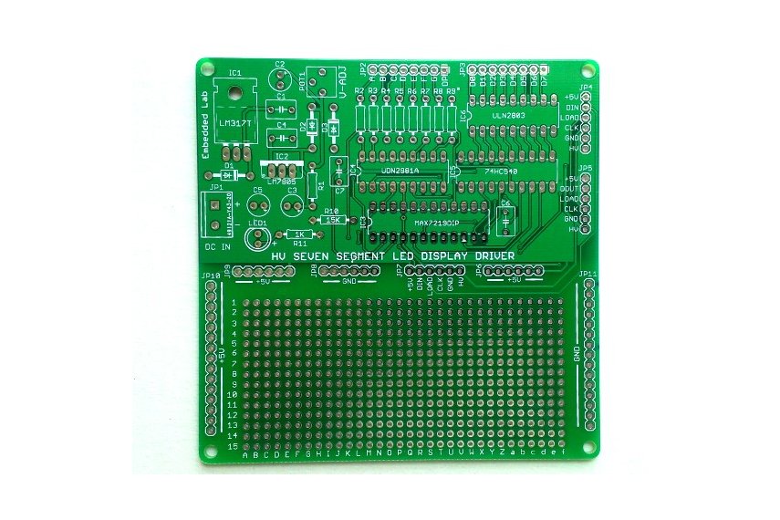
R3-R9 15R 1/2W resistors and R10 would be 150R (As DP have only 2 LED's in series). 7 segment big display is Common Cathode. Sorry guyz, for not providing enough information. I apologize for that. I have connected Disp 0 to RHS. That's correct, i made mistake in previous screenshot. Thanks for realizing my mistake:).
I have not used ULN2803 for sinking, as MAX7219 is capable of handling 500mA @ the most. For sink path. I have tried big display (2.3 inch Green color)before with MAX7219 but that was showing some serial data and it works great. I haven't tried making large counter using Controller with MAX7219. But this time i don't know why its getting off automatically after some time. Do i need to connect Resistors between MAX7219 and UDN2981?
You can bit-bang the SPI on PD5, PD6, PD7 or you can use the hardware SPI peripheral on PB2, PB3, PB5. Look at the example on Page 1. There are no 'current ratings ' for SPI signals. They are completely trivial. My data sheet says 320mA sink current IDIGIT and -40mA source current ISEG. My data sheet is '19-4452; Rev 3; 7/97' I would start with a 0.5' display. If you want to use BIG currents, use the 2.3' example.